
Top 10 RF Coaxial Connector Types for Global Buyers
Choosing the right Rf Coaxial Connector can protect signal quality, equipment life, and project budgets. Global buyers often compare connectors by appearance or price. That approach can fail quickly.
A connector may look identical to another model. Its impedance, plating, or sealing performance may differ. Small differences matter at microwave frequencies. A loose interface can create reflections, heating, and unstable measurements. Henry W. Ott, a respected EMC engineer, said, “The best way to solve a problem is to prevent it.” His advice fits connector selection closely. Careful specification prevents many expensive field failures.
This guide reviews ten common Rf Coaxial Connector types used across telecommunications, test equipment, aerospace, broadcast, industrial control, and wireless networks. It considers frequency range, impedance, VSWR, insertion loss, durability, environmental protection, and mating design. SMA, N-Type, BNC, TNC, SMB, MCX, MMCX, 7/16 DIN, and other formats serve different conditions. Some suit compact boards. Others handle outdoor towers, vibration, or high power.
There is no universal winner. Not even close. A connector that performs well inside a laboratory may disappoint on a rooftop. Buyers should verify drawings, cable compatibility, material declarations, test reports, and supplier consistency. Standards help, but they do not replace inspection. Even experienced teams sometimes overlook torque, bend radius, or connector gender. That is worth admitting. Reliable purchasing comes from matching the connector to the real installation, not merely copying a familiar part number.
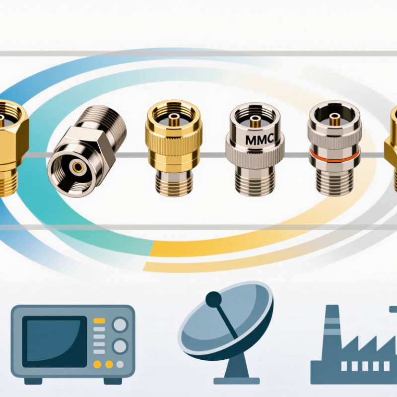
RF Coaxial Connectors: Function, Structure, and Core Specifications
RF coaxial connectors create a controlled path for radio-frequency signals. They join cables, antennas, test equipment, and communication modules. Their main function is simple: transfer energy while limiting signal loss, leakage, and reflections. Fit matters. A poor connection can weaken a strong design.
A typical connector contains a center contact, dielectric insulator, outer conductor, and protective body. The center contact carries the signal. The outer conductor provides shielding and completes the return path. Threads, bayonet locks, or push-fit mechanisms maintain mechanical contact. Seals help block dust and moisture in outdoor assemblies. Small details matter. Misaligned contacts may increase resistance and damage the interface.
Global buyers should verify impedance, operating frequency, return loss, VSWR, insertion loss, power handling, and temperature range. Common systems use 50-ohm or 75-ohm impedance, but they are not interchangeable without checking the application. Interface dimensions also deserve attention, especially when selecting among SMA, N, BNC, TNC, F, or UHF types. In practical inspections, I check plating, thread condition, contact spring force, and cable preparation. Overtightening remains a common mistake. A connector may pass a basic continuity test yet perform poorly at higher frequencies. For dependable sourcing, compare measured data with qualified datasheets and applicable technical standards. No single specification tells the whole story.
| No. | Connector Type | Primary Function | Basic Structure | Typical Impedance | Common Operating Frequency | Mating Mechanism | Typical Interface Material | Key Advantages | Common Applications |
|---|---|---|---|---|---|---|---|---|---|
| 1 | SMA | High-frequency signal transmission in compact RF assemblies. | Precision coaxial body with a threaded outer coupling, center contact, dielectric insulator, and cable or PCB termination. | 50 Ω | DC to 18 GHz is common; precision designs may support higher frequencies. | Threaded | Brass or stainless-steel body; gold-plated or similar conductive contacts are common. | Small size, reliable mating, good shielding, and strong availability in test and microwave assemblies. | Test equipment, antennas, wireless modules, radar assemblies, RF cables, and PCB interfaces. |
| 2 | N Type | Robust RF and microwave interconnection for cable, antenna, and outdoor systems. | Large coaxial connector with a threaded coupling nut, supported center pin, dielectric, and sealed outer body. | 50 Ω or 75 Ω | 50 Ω versions commonly operate from DC to 11 GHz; frequency depends on the design and interface. | Threaded | Nickel-plated or passivated metal bodies with plated center contacts; weather-sealed versions are available. | Mechanical strength, good environmental resistance, and relatively high power capability. | Base-station antennas, wireless infrastructure, RF test systems, outdoor radio links, and coaxial feeders. |
| 3 | BNC | Fast-connect RF, video, and instrumentation signal interconnection. | Coaxial body with bayonet locking slots, center contact, dielectric support, and cable or panel termination. | 50 Ω or 75 Ω | DC to 4 GHz is common; many general-purpose versions are specified below this range. | Bayonet | Brass or plated metal body with plated center contact; crimp, clamp, and solder styles are available. | Quick mating, clear locking action, broad availability, and suitability for repeated laboratory connections. | Oscilloscopes, signal generators, video equipment, instrumentation, control systems, and communication devices. |
| 4 | TNC | Vibration-resistant RF connection where a threaded alternative to BNC is preferred. | Coaxial construction similar in general form to BNC, but with a threaded coupling nut and improved mechanical retention. | 50 Ω | DC to 11 GHz is common for high-quality designs; the rated limit varies by construction. | Threaded | Plated brass or stainless-steel body with plated center contact and PTFE-type dielectric support. | Better vibration resistance than a bayonet coupling and stable RF performance in mobile equipment. | Vehicle radios, navigation systems, antennas, aerospace equipment, military electronics, and wireless infrastructure. |
| 5 | 7/16 DIN | High-power, low-intermodulation connection for demanding RF infrastructure. | Large precision coaxial interface with a robust threaded coupling, separated inner and outer conductors, and durable dielectric support. | 50 Ω | DC to 7.5 GHz is typical for standard designs. | Threaded | Heavy-duty plated metal body with high-quality conductive contacts and environmental sealing options. | High power handling, strong mechanical durability, low passive intermodulation potential, and outdoor suitability. | Cellular base stations, distributed antenna systems, broadcast transmitters, and high-power feeder cables. |
| 6 | SMB | Compact internal RF connection where rapid assembly and limited installation space are important. | Small coaxial body with a snap-fit outer shell, center contact, dielectric insulator, and cable or PCB termination. | 50 Ω or 75 Ω | DC to 4 GHz is common. | Snap-on | Plated brass or similar metal body with plated contacts; straight, right-angle, and PCB versions are common. | Compact footprint, fast assembly, and availability in through-hole, surface-mount, and cable configurations. | Automotive electronics, navigation equipment, telecom modules, measurement devices, and internal RF wiring. |
| 7 | SMC | Compact RF connection requiring stronger retention than a snap-fit miniature connector. | Miniature coaxial body with a threaded coupling, precision center contact, dielectric support, and cable or PCB termination. | 50 Ω | DC to 10 GHz is common. | Threaded | Plated brass or stainless-steel body with plated center contacts. | Small size, secure coupling, good vibration resistance, and useful performance at microwave frequencies. | Avionics, industrial controls, test instruments, communication modules, and compact RF assemblies. |
| 8 | MCX | Miniature RF and digital signal interconnection for space-constrained equipment. | Small coaxial body with a snap-on coupling, center contact, dielectric insulator, and cable or PCB termination. | 50 Ω or 75 Ω | DC to 6 GHz is common. | Snap-on | Plated metal body and contacts with cable, crimp, solder, or PCB mounting options. | Very compact, lightweight, quick to mate, and suitable for moderate-frequency RF assemblies. | GPS and navigation units, wireless devices, compact test equipment, automotive systems, and embedded modules. |
| 9 | MMCX | Ultra-compact RF connection for miniaturized wireless and embedded equipment. | Miniature coaxial body with a snap-on coupling, center contact, dielectric support, and cable or PCB termination. | 50 Ω | DC to 6 GHz is common. | Snap-on | Small plated metal body with plated center contact; right-angle and PCB-mounted versions are widely used. | Smallest footprint among common snap-on miniature types, low weight, and flexible cable routing. | Wearable electronics, compact antennas, wireless modules, portable devices, and embedded navigation equipment. |
| 10 | F Type | Low-cost 75 Ω connection for broadband television, satellite, and data distribution. | Threaded outer shell; the prepared coaxial cable center conductor commonly functions as the male contact pin. | 75 Ω | Up to approximately 1.2 GHz is common in many broadband installations; higher-rated designs also exist. | Threaded | Nickel-plated or zinc-alloy body with a plated interface; compression and crimp versions are common. | Low cost, simple installation, good shielding, and broad compatibility with 75 Ω coaxial cable systems. | CATV, satellite television, terrestrial television, broadband modems, and residential distribution networks. |